Click to join AmateurRadioMicrowaves
Join my Yahoo list for the latest "For Sale" items and general info on things 900 MHz and up!
Current Transverters I've built and have FOR SALE:
None at this time
Currently, I'm building up a homebrew beacon system for our local VHF/Microwave group. It consists of an apolLO I synthesizer
running at 1152 MHz, which will be multiplied up to 2304, 3456, 5760 and 10368 MHz with MMICs and pipe cap filters.

While at Microwave Update 2008 (Oct. 17-18, 2008) in Bloomington, MN, I bought a Down East Microwave 10 GHz-144 MHz transverter kit and matching 3W amplifier kit. I also ended up buying a set of circuit boards from W1GHZ for his 1296 transverter. I will post some pictures during their construction.

I use an old Icom-251A 2M all mode rig as the I.F. rig for bands above 902 MHz. I did a super easy modification to it to set the output power at the -5 to -8 dBm level. No worries about blasting my transverters! The mod can be reversed by simply re-fitting the jumper plug that I removed that removes DC power from the PA output transistors. It doesn't get any easier than that!
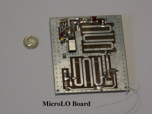
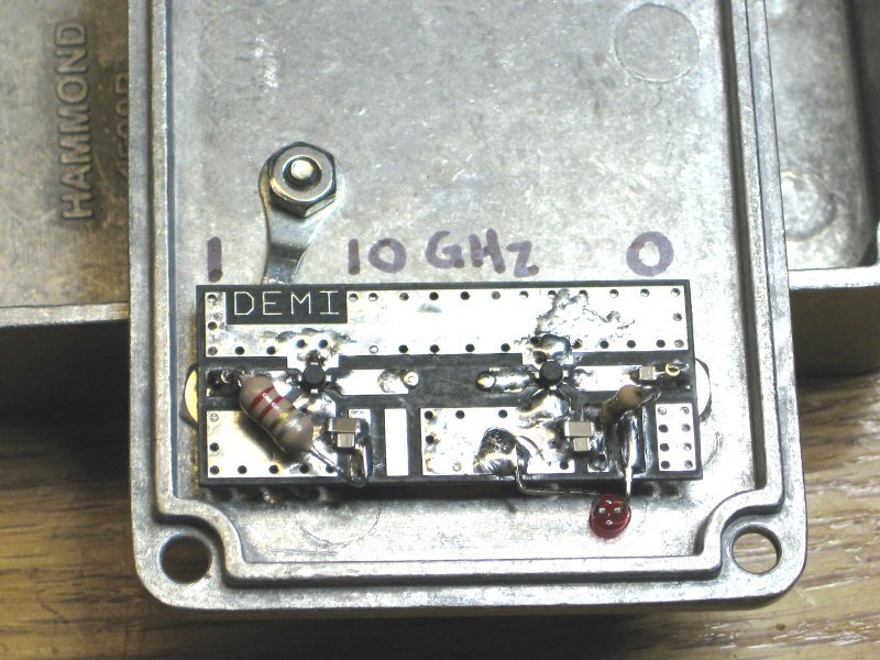
Here is the completed local oscillator board for the 10 GHz transverter, ready for initial voltage checks. It runs at 1136 MHz. Yes, some of those surface mounted components are small...and some even seem quite LARGE (the 1206 packages for example)!
UPDATE! Well, it's finally time to join the 21st Century. At Microwave Update 2013 in Morehead, KY, I bought the A32 synthesized L.O. board from DEMI and installed it.
No more guessing my 10 GHz transverter's frequency!
Here is the Transverter Control Board (mostly finished at this point). There are 3 relays mounted on the bottom of the board (not visible in this photo).
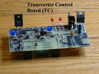
NOTE! When mounting the TC board in the DEMI aluminum case, check to be sure that the R2 potentiometer leads do not short to the enclosure. You may need to bend it back to ensure clearance.
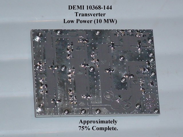
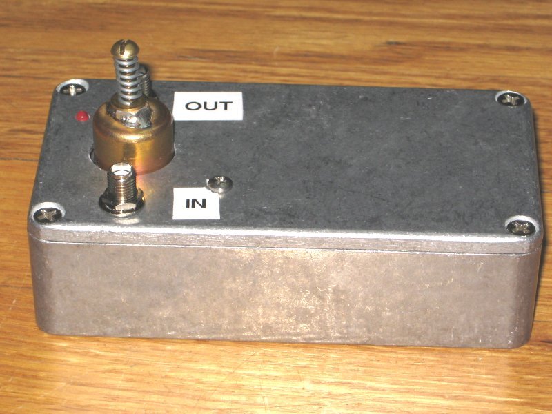
Here is the main transverter board. This is the low power (10mW output) board as I have their 3W amp that will be external to the transverter to further minimize LO drift due to case heating.
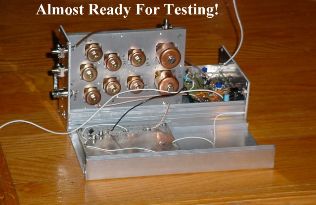
Here is the 10 GHz transverter, almost ready to start tuning those pipe caps! The board with the pipe caps is the main transverter board, the small board next to it is the TC (Transverter Control) board and the square board below in the other case half is the Local Oscillator board.
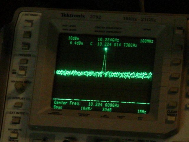
Here is the local oscillator output at approximately 10.224 GHz. Output level is at +8.34 dBm so it meets specs of +7 dBm minimum. That is good news! The output is very clean. The closest harmonic of the LO board is at 6.8 GHz is about 36 dB down from the LO signal. More than good enough!
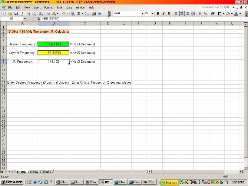
As I was doing the initial testing (more like observing) I noticed the LO frequency was drifting quite a bit. The crystal has a thermistor soldered on to its case with 9V fed to it to provide heat. After an hour or so (as noted in the documentation) it settled down and became quite a bit more steady. This is the "burn in" phase and needs to be accomplished before trying to net the crystal on frequency. If you try to net it before the crystal "ages" at temperature, you're just going to be chasing the frequency around every few minutes! The documentation actually calls for adjusting the trimmer capacitor for maximum output power from the oscillator rather than zeroing the crystal frequency. This is probably good advice. If you are not set at maximum power, the crystal may not start up when cold or may quit out in the field as the temperature changes. Been there, done that, with a 10 GHz transverter I borrowed from a friend. However, it just bugs me to have to set my IF rig to something other than 144.100 to get 10368.100 out. So, I'm going to TRY netting the crystal and see how it goes. One modification I think is good is to tap off some of the crystal frequency RF and bring it out to the spare BNC connector on the case so the LO frequency can be measured easily. Then I can hook up a frequency counter in case the oscillator stops running so I can at least see when I get it started back up and get it back on a known frequency! I modified the MicroLO by adding a 1.8 pF capacitor (it was the smallest value I found quickly) to the junction of C11 and L3 as noted in the DEMI documentation. I connected the other end of this capacitor to the center conductor of a leftover piece of the mini-coax and brought it out to the spare BNC connector on the case. I grounded the coax shield at both ends. The shield at the LO board end is grounded to the circuit board ground next to the place where the 1.8 pF capacitor is and holds the coax in place. I ran the coax out away from the board and then over the ground plane side so that the coax was not laying across the LO board printed filters, possibly detuning them. Seems to work fine! I may have had the LO netted on the kitchen table at 70 degrees, but it will most likely be somewhere else when at 40 degrees in the field, so it will be nice to have access to the oscillator frequency. I'll have a little Excel spreadsheet running on the laptop so I can enter the crystal frequency and it will automatically tell me what I.F. frequency is required to hit my target 10 GHz frequency. Not really needed, just a nicety! Something as simple as this...
I finished up testing on the transmit side tonight (Dec. 3, 2008) and it is putting out +10.5 dBm at 10368.100 MHz. Spec calls for +5 dBm minimum, so I'm good to go!
Now I have to beg, borrow or steal a weak signal source so I can tune up the receive side. Donn, WA2VOI, (ONE OF THE MANY GREAT GUYS FROM THE NORTHERN LIGHTS RADIO SOCIETY
) is loaning me his weak signal source, so I should be able to get the receive side done soon. (UPDATE: December 5, 2008. I got Donn's weak signal source and have finished tuning the receive side of the transverter. It's
ready to go on the air!) Here is my latest "hack job" so that I have my own signal source for testing my present (and future) DEMI transverters (for 2.3 GHz and up).
It is basically a DEMI MMICKE2 two stage generic amplifier board kit. The kit with the board and two ERA-2 devices is only $14 (March 2009). I ordered a pair of DEMI's N6 MMICs
as they are good to 10 GHz and substituted them in place of the ERA-2 devices. I removed the one trace on the middle of the board that was common to the two coupling capacitors between the
stages. This leaves the ends of the remaining traces about 5/16" apart. I drilled a #59 hole at the end of each trace and inserted a common household straight pin that has been cut to an overall length of 3/16".
Each pin is a probe for a copper pipe cap filter. The pipe cap is soldered to the groundplane on the back of the board, centered over the probe pins. These are the same thing that DEMI uses in their 10 GHz transverters.
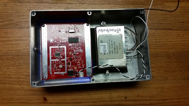
I will be using a W1GHZ 1152 MHz local oscillator board to drive these hack jobs. Each band will have its own circuit board and corresponding pipe cap filter. So far, I only have the 10 GHz one made up.
I have a few parts to get yet to finish up the L.O. board and I need to get a pair of 68 Ohm 1206 size chip resistors
to bias up the N6 devices. I'll report on the sucess or failure of the project when I finish it up. Until then, here is what I have so far...
Update on the harmonic generator shown above...As I was tuning, I could see various harmonics EXCEPT a signal at 10 GHz. As I tune the pipe caps, I can hear the 10 GHz signal through my transverter, but it is just audible above the background noise. When I peak the filter on any of those other harmonics, the 10 GHz signal seems to disappear. Scratching my head on this one! Update 2. I think I may have found the issue with the lack of a 10 GHz harmonic. I mis-read the W1GHZ article on the 1152 MHz L.O. I thought it was supposed to put out ~ +5dBm from the L.O. board. It is ACTUALLY supposed to put out around -5 dBm. It gets amplified to the +5 dBm level on the transverter board. I needed +5 dBm out of the L.O. board, so I added an ERA-2 MMIC to the unused pads already present on the L.O. board. I am now getting +5 dBm out of the L.O. board, which should be enough to overdrive the first MMIC in the harmonic generator. I will confirm this today on the spectrum analyzer. Update 3. With the drive level now at +5 dBm, the harmonic generator is working. Output at 10 GHz is about -74 dBm.
Today (December 14, 2008) I started building the PA module (3 Watts). I got it about 90% finished. Here it is awaiting a couple more parts and the RF device.
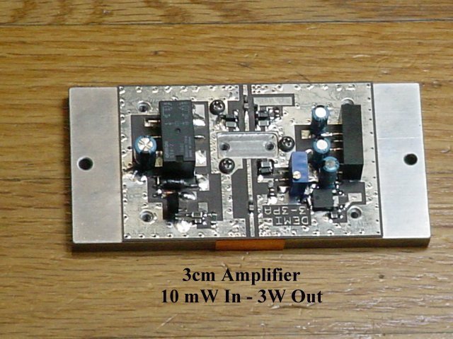
Here is the completed system (December 21, 2008). All testing is done and the unit is ready to go on the air. I have the PA set to 2W output. If heat dissipation is satisfactory at that level, I may increase it to the design level of 3W. During testing, I briefly tested the PA by increasing the drive to the full output level from the transverter (10mW) and was able to read 4W on the power meter.
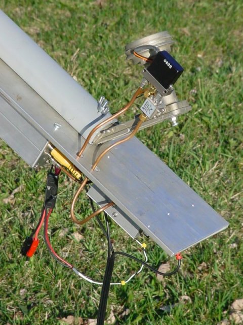
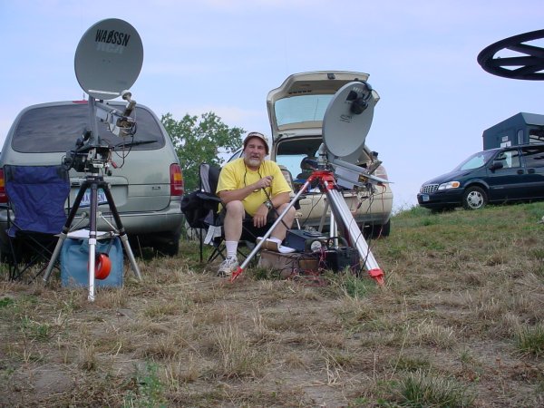
Here is how I have everything mounted to the dish for portable operation.
Here I am during a break in the action during the second weekend of the 2009 ARRL 10 GHz and Up Contest, operating from EN34ir.
My 432 beacon update is now completed. It started out as a low power beacon at about 75 mW. I just finished installing a Mitsubishi
M67749M PA module. The output is set to 4 Watts. The beacon operates on 432.324 MHz from EN45fa.
The DEMI circuit board comes empty and can be used with various RF PA "Brick Modules" by just bending the leads of the module slightly to fit the PC board pads.
Antenna is an M-Squared 432 HoLoop at 30 feet above ground. Reception reports appreciated!
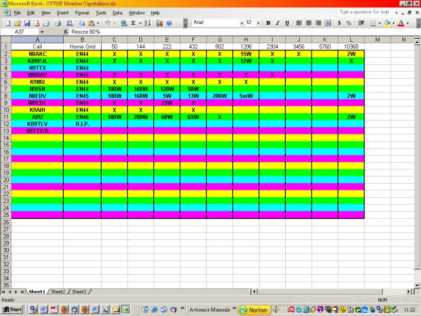
Here are the capabilities for members of the Chippewa Valley VHF Contesters. Our group is centered on Eau Claire, WI.
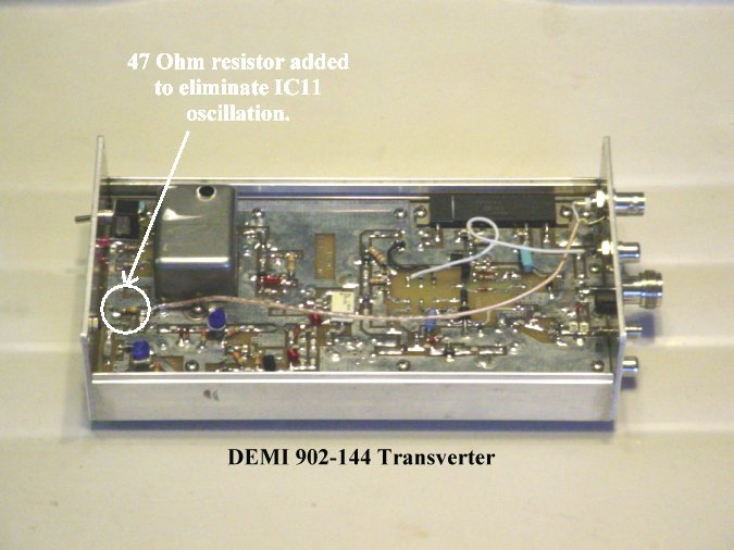
Just in time for the 2006 September ARRL VHF QSO Party Contest, I finished building a Downeast Microwave 902 MHz transverter.
The assembly process went very well. The only bug was that one of the PIN diodes in the I.F. section switching circuit was open.
This was discovered during tune up procedures the day before I was to leave for our trip to EN67 to operate. No time to get one
from DEMI. Bruce, W9FZ came through, though. He was going to be up in EN67 to start his rove and brought me a generic PIN
diode. I repaired it in the field and it worked. I could only get about 5 or 6 Watts out. It should be about 10 Watts. Upon
pondering the situation, I think it might be because I'm powering the unit with 22 gauge wire. It was supposed to be temporary, just for tuning up the receive
side and the L.O., which doesn't draw much current. I will change that before I rip into it much further! This should be a fun band!
(Update: with 18ga wire, the output power is running at about 8.5 Watts now).
After going through a more thorough setup of the transverter, I noticed that while keying the transverter PTT line with no RF applied, I was getting about
5 Watts output at about 915 MHz on the spectrum analyzer. It turns out that the problem was in the optional MMIC I had installed on the board
that is the first one in the TX chain. I needed to use this MMIC since my IF drive level is between -5 and -8 dBm from my modified
Icom IC-251A. It appears the MMIC was oscillating, so I put a 47 ohm, 1/4W resistor across the IF input coax so that
there was always a load on the input. This cured the problem.
I have a Motorola cellphone solid state amp that I will start
converting after the 2009 New Year.
This should help get a little DX on 902! Once I get it modified (simple) and running, I will post more info here about it.
It runs on 24 Volts and I picked up a LaMarche 24V commercial battery charger at a hamfest that I will use to power it. I have the amp finished
and am getting 200 Watts out with less than 5 Watts of drive.
Now, how about this?
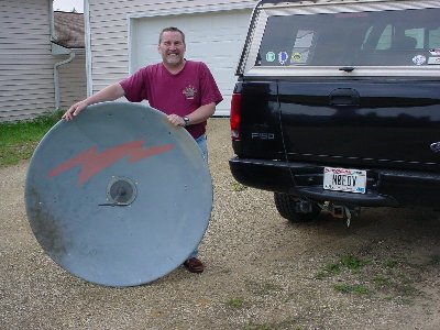
Another ham acquaintance gave me this dish and has two more 6 footers for me! Planning to use this one on 902 MHz. Should have a
gain somewhere in the neighborhood of 18dBi.
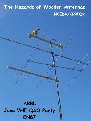
How's this for intimidation? Joe (AI9Z, ex-KB9IQR) and I were operating the ARRL June VHF QSO Party Contest (2006)
from grid EN67, a rare grid from the U.P. of Michigan, near Copper Harbor. We set up on top of Brockway Mountain, 726 above
the Lake Superior water level. We attracted the attention of this hawk and he tried to scare us off. He was flying right at us
at about 3 feet above the ground and pulled up and landed on my homebrew 432 Quagi, which is made of wood.
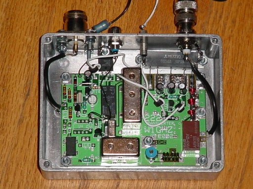
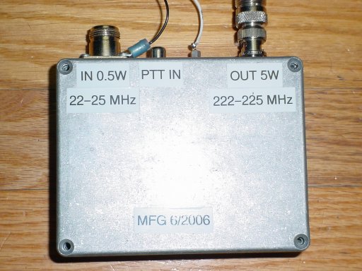
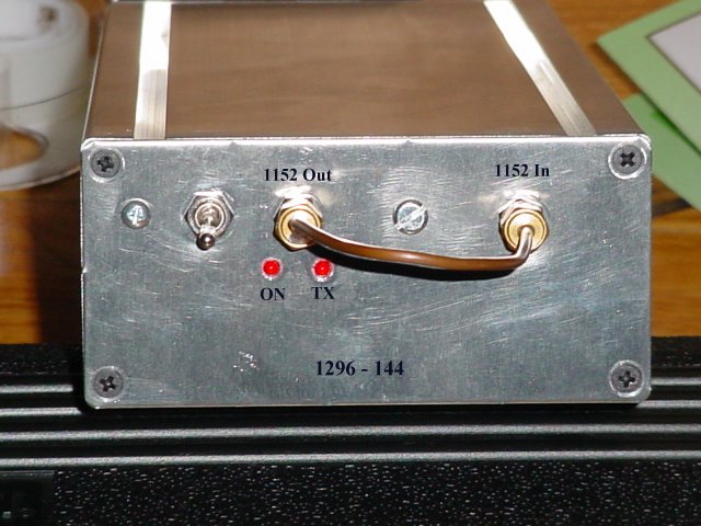
One of my other completed equipment projects (June 2006) is for the 222 MHz band (W1GHZ transverter). See
W1GHZ HomePage for a copy of the construction article.
As any good experimenter does, I modified the original design to suit my wants and desires. The things I changed were the local
oscillator frequency from 198 MHZ up to 200 MHz, and changing the 2 pole helical filter (TOKO) to a 200 MHz center frequency, but probably not really necessary.
I bought it from Down East Microwave. I don't see it listed in their catalog now, but you might call them to see if they can still get it. The reason for the change is so that
it would be easier to figure the output frequency (IF = 22.100, output = 222.100) just in case I use it with my Kenwood 690S. I normally
drive it with my Yaesu 857 which has a cool feature. You set the IF frequency and then go to the XVTR A (or XVTR B) setting in the menu
and dial in what you want the display to show when you select XVTR A (or XVTR B) to "On". Now the LCD readout on the 857 shows 222.100, even though its
real output is 22.103 MHz in my case (the LO uses an IC oscillator with no adjustment, so you get what you get for an LO frequency...mine is 3 KHz low of 200.000 MHz
so I set the IF to 22.103 MHz to come out on 222.100 to match the display. Pretty slick, eh? The other mods I did are no LEDs to reduce power consumption
to bare minimum. I know when it's powered up, I know when the IF rig is set to use with it and I know when I have the mic keyed. I also completely
removed all of the circuitry used to detect the IF band (the transverter was designed to mate with a Yaesu FT-817).
![]()
![]()